Cš-L is a dual voltage controlled oscillator.
It takes the modern approach of dual primary oscillators and expands upon them.
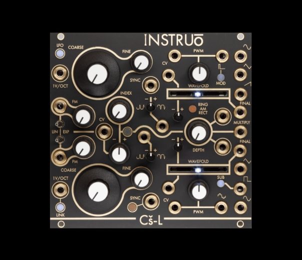
Each oscillator sports its own wavefolder, PWM output and wide range of classic waveforms.
A four-quadrant multiplier stage allows for ring modulation as well as rectified and positive only amplitude modulation.
Each oscillator uses a different core (top sawtooth core, bottom triangle core) giving the best of both worlds.
A versatile, definable routing modulation bus allows for CV control over a huge range of cross modulation without even needing to insert a patch cable.
A built in signal multiplier allows for ring modulation as well as full and half-wave rectified amplitude modulation.
Cš-L | siː-əz-ɛl | proverb (derivative) “complex sauce-later” (see Tš-L )
Size
26HP
Depth: 35mm
Power
+12V: 150mA
–12V: 80mA
Specifications
- Sawtooth core voltage controlled oscillator (Oscillator A – Top)
- Waveforms: Sine, Triangle, Sawtooth, Pulse, wavefold final
- Triangle core voltage controlled oscillator (Oscillator B – Bottom)
- Waveforms: Sine, Triangle, Square/Sub, double pulse, wavefold final
- 1V/octave, Coarse and Fine pitch controls per oscillator
- Frequency modulation input per oscillator, linear or exponential response, with attenuators
- LFO range switch for oscillator A
- Switchable link between 1V/octave inputs for parallel tracking
- Multiply output with three modulator behaviour options
- CV over each wavefolder with attenuverters
- Symmetry offset control for each wavefolder with attenuverters
- CV controllable modulation bus (INDEX) with versatile definable internal routing
Description
Complex oscillators traditionally comprise of two VCOs configured in ways to generate complex waveforms. The classic configuration uses an arrangement of modulator -> carrier. Use of wavefolders enhance the timbre complexity to a ‘final’ output. The Cš-L takes this tried and tested configuration, but blurs the lines of which voice is the carrier and which is the modulator. They can be either or both simultaneously!
Each Oscillator has it’s own unique characteristics and perks, down their core circuits. There is a wavefolder per oscillator, giving the Cš-L two entirely separate ‘final’ outputs.
Oscillator A (Top) is a sawtooth core voltage controlled oscillator which produces sine, triangle, sawtooth and pulse outputs. The pulse is a classic variable duty cycle waveform. The LFO button will insert a negative DC offset to the oscillator’s frequency control. This reduces the range into LFO territories. The SYNC input hard syncs the oscillator’s waveforms which allows for classic hard sync tones when running at audio rate. In LFO mode the sync input can be used to force waveform resets. Very useful when clocking LFO shapes.
Oscillator B (Bottom) is a triangle core VCO. It has a slightly different set of waveforms to A: sine, triangle, square/sub and a double pulse with variable pulse width. The SUB output can generate a square wave at the oscillator’s fundamental frequency, 1 octave below, or 2 octaves below. The button switches the octave and illuminates to identify the current sub state. The SYNC input for Oscillator B is a soft sync control which inverts the triangle core’s charge direction on an impulse. This allows to tuning to unisons with other voices with frequency locking precision.
The SYNC button will choose internal soft syncing of oscillator B to oscillator A (lit yellow), or hard sync of oscillator A to oscillator B (lit white). Note that with A hard sync’d to B, the SUB square output is used as the clocking signal which means changing octaves can be used to affect sync ratios.
The LINK button activates a cross normalisation between the oscillators allowing for a single control voltage signals to be used at either 1V/OCT input to control both voices in parallel.
The MULTIPLY output uses the sine waves of both oscillators normalised to the corresponding input jacks. The button alters the affect of the signal inserted at oscillator A’s input. It selects between RING, AM and RECT.
RING is full 4-quadrant amplitude modulation, more commonly referred to as ring modulation.
AM removes any negative voltage in the modulator signal, allowing only positive voltages to control the amplitude.
RECT rectifies any negative voltage, inverting it to positive.
Each amplitude modulation type has it’s own distinct sonic character with differing makeups of sideband frequencies.
The multiplier section can be used with any signals allowing for implementations entirely isolated from the Cš-L if desired.
The INDEX control utilises two internal VCA’s used to control the amplitudes of branches of each oscillators’ sine wave.
These modulation signals can be routed internally to the opposite oscillator’s FM input, wavefold CV input, wavefold symmetry input, or PWM CV control.
The INDEX pot (and attenuvertable CV input) controls the depth of both oscillators’ sine waves simultaneously for use as a complex cross modulation bus.
The WAVEFOLD faders control the amplitude of each oscillators’ sine waves via exponential response VCAs.
These can be ‘struck’ with external envelopes for classic west coast plucked sounds.
The fader full left will silence the FINAL output. Centred, it will raise the amplitude to a sine wave and beyond that will fold.
When not receiving from the modulation bus, the wavefolder symmetry controls receive a DC reference voltage that can be used to bias the sine waves before hitting the wavefolders.
Enabling the modulation bus to the symmetry control will effectively sum a scaled/inverted version of the opposite oscillator’s sine wave with the primary’s, before the wavefolder. This can also be used to mix any external signal with either of the oscillators’, pre wavefolder.
The results are rich and bell-like but without the a-tonality of FM
With very minimal patching, results can be extremely rich and… complex!
IDR 9.435.000

