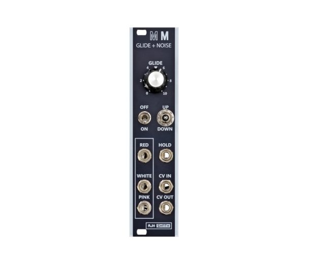
There is a lot of power and funtion contained within this deceptively small 6hp module. It features both the Glide and the Noise generator circuitry from the vintage Model D synthesiser, and we have now improved the performance and added extra features in the new Mk 2 version
The MiniMod glide uses a discrete circuit which includes a track and hold function that can gate the glide effect. Glide is only active when the Hold CV input is high, so if the hold input is connected to the gate output of a Midi/CV convertor then the glide will be active only while the key is actually depressed, emulating the exact behaviour of the original Model D synthesiser.
We have also increased the versatility of the module by adding Glide Up only and Glide Down only modes in addition to the standard Glide Up & Down mode of the original circuit,
The Noise Generator is completely separate from the Glide circuitry. There are three outputs offering White Noise, Pink Noise and Red Noise. The noise source itself is all analogue and uses a specially selected transistor in avalanche mode which is amplified and filtered by discrete transistor based circuitry.
Module Width: 6hp
Module Depth: 24mm
Current Usage: 36mA Positive, 38mA Negative
In Depth
This information is for the new Glide Noise Mk2 module, for information on the previous Glide Noise Mk1 module click here.
Changes implemented on the new Glide Noise Mk2
The original MiniMod Glide +Noise module was based exactly on the original Minimoog Model D circuitry, which was designed to be used with the built in Model D keyboard, and because of its vintage design its range was severely limited to 5 or 6 octaves, and it also responded to positive voltages only. A further limitation was that it would not return fully to zero when selecting long glide times, which restricted the range even more.
So we made the decision to re-designed the MiniMod Glide + Noise using modern precision parts, and we have come up with an all new circuit which has exactly the same function, but with a hugely extended range. It now has an impressive 14 octave range, and can respond to negative voltages down to -5V. This is a very useful feature, as our MiniMod VCO’s will respond to negative control voltages and produce correspondingly low frequencies; so it is now possible to glide down quickly or slowly to crazy sub bass levels! The hold feature has been improved too, it covers the full audio range as well as DC control voltages, and works as a track and hold module with Eurorack signal levels.
A further enhancement is that the Mk2 module can now (using selectable jumpers) transmit or receive pitch CV to the Eurorack power bus; for example the Glide CV Output can now be directed to the Bus in order to send CV’s to (for example) three VCO’s via the bus without the need for a passive multi and four patch cords!
The Noise section of the module is unchanged, except that we have slightly boosted the level of the Red Noise output to bring it more in line with Eurorack control voltage levels.
Lastly, it is much shallower – Mk1 Glide Noise had a depth of 54mm, and it was the only MiniMod module that was too deep to fit a skiff style case – and this prevented a full MiniMod system being installed into a shallow Eurorack case. The new MK2 version is only 28mm deep, so this allows both it and a full MiniMod system to be mounted into shallow skiff style Eurorack cases
The Hold behaviour
Originally the glide circuit was part of the keyboard controller and the glide effect was only active while one or more keys were depressed, as soon as all keys were released the hold circuit came into effect and held the CV voltage at a constant level and disabled the glide. This state was held until there was another key press, upon which the glide effect resumed.
Three Glide Modes
We have added a very useful extra feature which was not available on the Model D – we can select Glide up only, Glide down only or both. So, for example in “glide up” mode, if you play a higher note then the sound will glide to that note at a speed determined by the glide control, but if you play a lower note the sound will disregard the glide setting and jump immediately to the lower note. The opposite effect is available in “glide down” mode. These modes are available in addition to the existing glide mode which is selected whith the switch in its centre position.
Integration with the Eurorack Power and Distribution bus
With Eurorack power distribution, in addition to the+12v, -12v, Ground and +5V rails we have two extra rails that allow the distribution of Pitch CV and Gate signals, and using these can reduce the number of patch cables required if modules use this feature, as these signals can be automatically routed between modules. Almost all Midi to CV converters are able to transmit Pitch CV and Gate signals to the ditribution bus, and these signals can be received by the Glide Noise Mk2 modules.
Gate Bus control
The MiniMod Glide has a gate input which can be connected to the gate output of Midi/CV convertor (or any other gate/trigger signal) to allow the Gated Track and Hold mode. If nothing is plugged in to the gate jack then the input is normalled internally to the +ve rail so that the gate is held in a high (on) condition. Therefore glide is permanently active, with no hold available unless the front panel Hold jack socket is used..
A jumper on rear of the modules allows the gate signal to be taken from the Eurorack bus if desired.
To select normal Glide behaviour set the GATE input selection jumper (see above) to ON position. In this position HOLD is not active unless an external GATE is connected to the HOLD input.
To enable control of the Gated HOLD from the Distribution Bus, set the GATE input selection jumper to the BUS position as shown above. This way the Glide Noise Track and Hold will respond to Gate signals on the Distribution bus.
Pitch CV Bus control
We can whether Pitch CV is transmitted or received from the distribution bus. Note that it cannot transmit and receive at the same time, as the distribution bus would require an extra channel for that.
To Receive pitch CV from the Distribution Bus:
Set the PITCH CV jumper cap as shown above (IN position) In this configuration, if a MIDI to CV converter or Sequencer is configured to transmit a pitch CV signal to the Bus, then this will be received by the CV IN input of the Glide Noise modules, and this saves a patch cable as the Pitch CV does not need to be connected to the fromt panel CV IN Jack socket..
To Transmit Pitch CV from the Glide Noise module
Set the PITCH CV jumper cap to the OUT position. This will connect the CV out from the Glide Noise Module to the Distribution bus, this is very useful if you have two or three MiniMod VCO’s and you would like them all to have Glide applied to their Pitch CV’s – the CV OUT of the Glide is routed to the Distribution Bus, and as the 1V/Oct inputs of the VCO’s are normalised to the pitch CV on the distrinution bus, then all three VCO’s will receive the Pitch CV signal. Patching a cable to the 1V/Oct input on the VCO disables this normalising, this is useful if you wish to have a VCO free running – for example when using a VCO as an LFO.
The CV OUT on the Glide Noise module has a “zero impedance” output stage and can drive up to four VCO’s simultaniously, so it should not be necessary to use an active Buffered Mulit to split the signal. By using CV Transmit to Bus we save three patch cables and a multi to split the signal
It is VERY IMPORTANT to ensure that no other modules are already configured to transmit a CV signal to the Pitch CV to the Distribution Bus, so with modules such as Midi to CV converters do ensure that they are configured NOT to send CV signals to the BUS, otherwise you will have two conflicting PITCH CV signals routed to the Ditribution Bus which will interact with each other and produce very unpridictable pitches from your VCO’s!
Noise module
White Noise, Pink Noise and Red Noise are simultaniously available from their respective outputs. The White and Pink noise can be used as both audio or random CV signal sources, whereas the Red noise is mostly useful at sub audio frequencies and is commonly used as a random CV voltage source.
The noise source itself is all analogue and uses a specially selected transistor in avalanche mode which is amplified and then filtered by discrete transistor based circuitry. We carefully select the npn transistor that we use as a noise source by measurement and analysis using a 24bit Audio range Spectrum analyser, this method allows us to select transistors with exactly the same noise signature as the original.
IDR 4.114.000


